|
There are four key diagram types that provide the component design for a Business App, an IT App, or a Service.
Base Diagram
A Base Diagram is the (EA)<sup>2</sup> term for a diagram that contains the image of its subject element (in this case the Business App) in the form that you will want to use most of the time. See Dragging Elements from the Project Browser for more information.
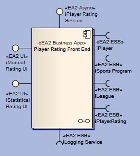
For Business Apps, this diagram is used to show the exposed interfaces provided and required by the component, thus eliminating the need for you to add them to the diagram whenever dragging the Business App onto a diagram. The Business App appears as a black box with no details of its inner workings. There are two versions depending on the amount of detail you wish to capture.
You can model Business Apps as black boxes. This is approprate when you are using third party products and do not know their inner workings. In this case, you can put exposed interfaces directly onto the Business App. On the other hand, you may want to see the components that comprise the Business App. This is especially true if you develop your own applications.
The diagram below shows a Business App as a black box with the interfaces directly on the application. We do not know the internal workings of the application.

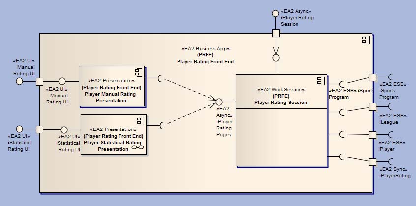
The next diagram shows the white box approach. Ports, with the exposed interfaces that realize the same interfaces as in the black box diagram, are used to show that there are internal components that connect to the applicaton's exposed interfaces.

If we open up the Business App to see what is inside, we will see internal components connected to the exposed interfaces, as shown below.

As mentioned above, Enterprise Architect has a nice feature that eases the task of displaying all of the embedded elements of a component. You can use the look of a component from another diagram to draw it on the current diagram (see Dragging Elements from the Project Browser). To leverage this capability, we apply a diagram naming convention that uses a dash in front of the component name for a component's base diagram. Then, whenever we need to drag the component onto a diagram, we can easily find its base diagram in the list of diagrams we can choose from.
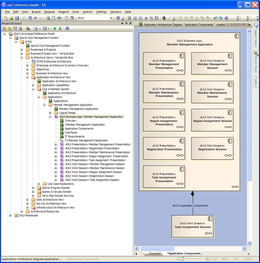
The following diagram shows all of the compnents of the Member Management Application sans interfaces. The purpose of this diagram is simply to organize all of the components and make sure they are connected to the owning Business App. The Business App is composed of numerous Presentations and Work Sessions. The Task Assignment Session has been moved off the Business App in order to show the <<EA2 Application Component>> connector that must be drawn between the two in order for the SQL views to pick them up.

|